F4F fuel indicator hook up
Mon Dec 17, 2007 2:02 pm
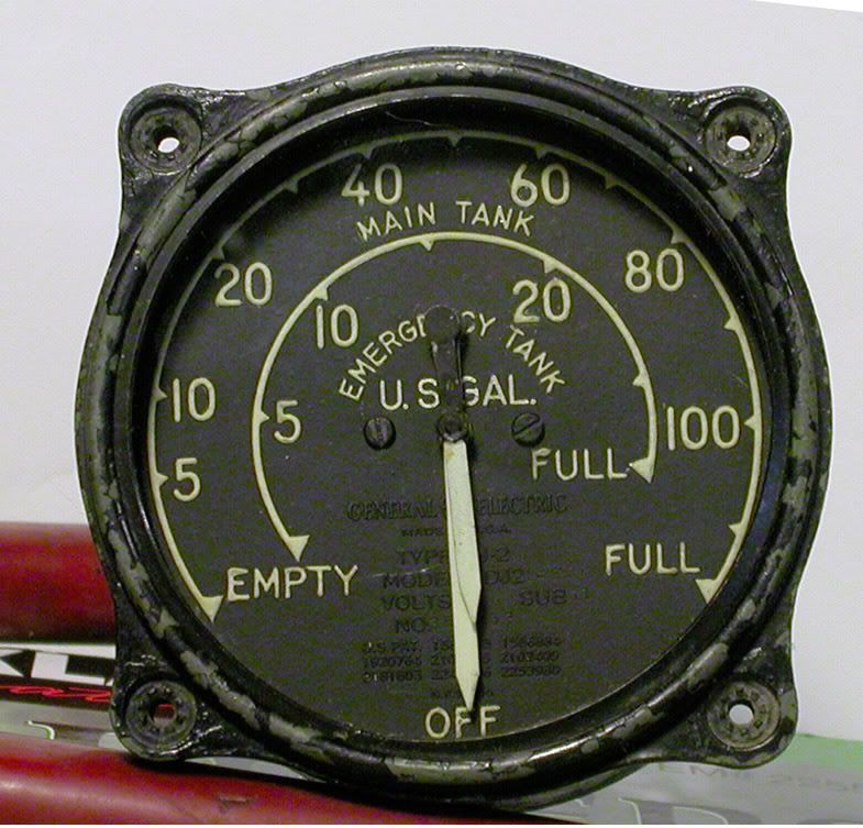
I THINK this is from an F4F Wildcat. I have seen it in cockpit photos, but I have also seen a 24 volt version without the Reserve scale.
This one is 12 volt. I want to make it work in my hot rod. Is there a maintenance book that I can look in for wiring? I can make the needles move by putting 12v to some of the pins in the amphenol plug, but I am not sure how Aircraft fuel senders work. Is it the same as automotive applications that vary the ground (neg) connection?
Thanks, Dave
Mon Dec 17, 2007 6:01 pm
This gauge is listed as being used in the FM-2 in my General Electric fuel gauge guide. Not sure of the hook ups though.
Cheers,
Richard
Edit... sorry. This is not the gauge I thought it was. Went off the cuff, and should have checked. What is the part number it's 8DJ2-??? I don't have listings for all of these, but might still have something on it for you.
Cheers,
Richard
Edit... sorry. This is not the gauge I thought it was. Went off the cuff, and should have checked. What is the part number it's 8DJ2-??? I don't have listings for all of these, but might still have something on it for you.
Mon Dec 17, 2007 6:30 pm
Should be a minimum of three pins and a maximum of eight, depending on the internal design. Standard design practice was to use single wire sending units. Power to the gauge was fed through the indicator circuit and down to the sender. From there it went to ground. The senders were just big variable resistors that were controlled by float position via gear drives. For a minimal design the gauge would have the following:
Power
Lead to one sender
Lead to second sender.
If it was by chance a two wire design, then the ground would be provided by a return wire that would correspond to each indicator circuit. You would then have:
Power
Gauge ground
Lead to sender one
Return from sender one
Lead to sender two
Return from sender two
In the case of a lighted gauge, add either one or two more leads, providing the circuit for the internal lighting, or, in the case of some instruments, there was a completely independent circuit with a bulb that plugged into the gauge case.
You might have to get you a little DC to DC converter to power it, and a resistor for current limiting, depending on the required current draw to drive the indicators to full deflection with any accuracy. If you can find a small 10 turn pot that is about the same value as the sender you are going to use, it would be easy to test it on the bench. You might need to do some load adjustment to make it work right.
Power
Lead to one sender
Lead to second sender.
If it was by chance a two wire design, then the ground would be provided by a return wire that would correspond to each indicator circuit. You would then have:
Power
Gauge ground
Lead to sender one
Return from sender one
Lead to sender two
Return from sender two
In the case of a lighted gauge, add either one or two more leads, providing the circuit for the internal lighting, or, in the case of some instruments, there was a completely independent circuit with a bulb that plugged into the gauge case.
You might have to get you a little DC to DC converter to power it, and a resistor for current limiting, depending on the required current draw to drive the indicators to full deflection with any accuracy. If you can find a small 10 turn pot that is about the same value as the sender you are going to use, it would be easy to test it on the bench. You might need to do some load adjustment to make it work right.
Tue Dec 18, 2007 10:17 am
Thanks for the info guys. I will get the part number off of it tonight. It would be great to know what plane it came from for sure. Can't even think of how many cockpit photos I've looked at to find one with this gauge.
Armed with this info I will put it on the Frankenstein test bench and fire up the 3-ball generator. Maybe I can bring it life.
Thanks again. Dave
Armed with this info I will put it on the Frankenstein test bench and fire up the 3-ball generator. Maybe I can bring it life.
Thanks again. Dave
Wed Dec 19, 2007 3:27 pm
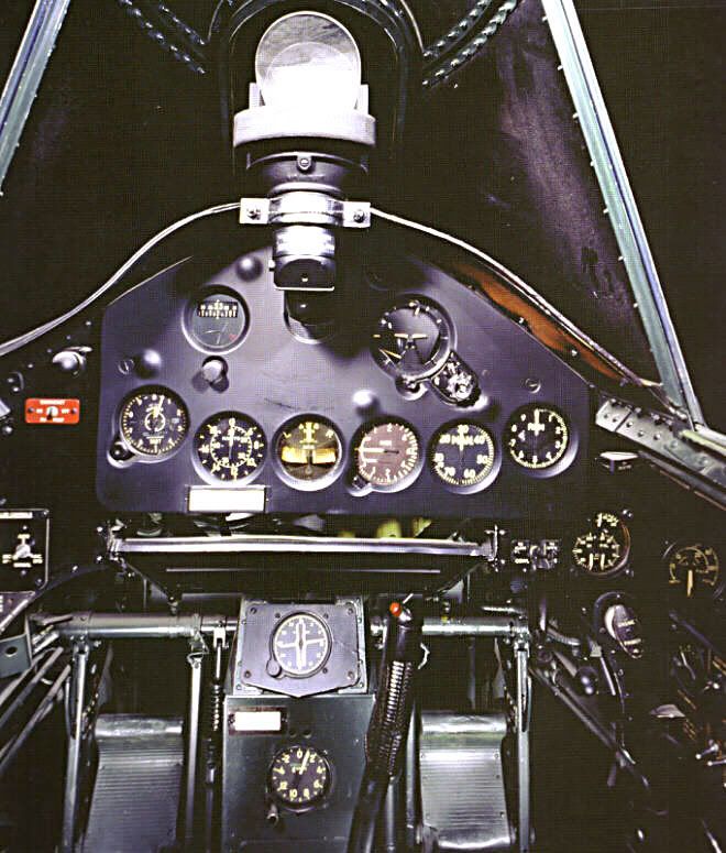
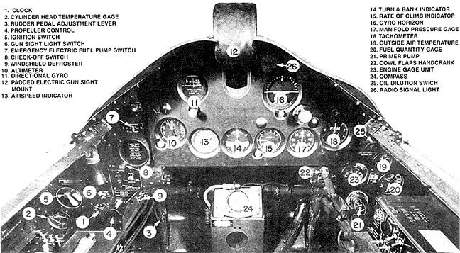
Here are a couple shots from uscockpits.com that I found. I think they show the above dual gauge in a F4F and in an FM-2 layout.
Thanks Richard for checking the model number -8DJ2-LBC.
Thanks Richard for checking the model number -8DJ2-LBC.