Warbird Information Exchange

DISCLAIMER: The views expressed on this site are the responsibility of the poster and do not reflect the views of the management.
It is currently Fri Apr 19, 2024 6:16 am

All times are UTC - 5 hours


Classic Wings Magazine WWII Naval Aviation Research Pacific Luftwaffe Resource Center
When Hollywood Ruled The Skies - Volumes 1 through 4 by Bruce Oriss


Post new topic Reply to topic  [ 1022 posts ]  Go to page Previous  1, 2, 3, 4, 5, 6, 7, 8 ... 69  Next
Author Message
PostPosted: Sun Nov 16, 2008 3:40 pm 
Offline
User avatar

Joined: Tue May 16, 2006 10:06 am
Posts: 858
Location: Midland, Texas
While visiting with Dave Miller today out in the CAF hangar, I noticed he was working on somthing different and took the following picture to post as a "what is it" quiz. There are two components to it as shown.

You know where it was and I will tell you it is related to our B-29 FIFI but that all for now. Dave is pretty busy but hopes to have one of our local High Sky Wing members who is a very good photographer start to help him document further work on FIFI in the near future. For now, I'll try and monitor your answers. Have fun.

Image

Randy


Top
 Profile  
 
 Post subject:
PostPosted: Sun Nov 16, 2008 4:02 pm 
Offline
2000+ Post Club
2000+ Post Club

Joined: Fri Sep 21, 2007 6:25 pm
Posts: 2760
When Testaclese gets finished will you be able to test other engines on it besides the -3350? In other words, will that test stand be able to be used on other projects, or is it being specifically built for FIFI's new engines only? If so, will it require much modification to work with non-3350 engines? How much work and what will it entail?

Thanks for the info, guys! This thread is very fascinating! :D


Top
 Profile  
 
 Post subject:
PostPosted: Sun Nov 16, 2008 4:18 pm 
Offline
User avatar

Joined: Tue May 16, 2006 10:06 am
Posts: 858
Location: Midland, Texas
If I may post a reply from what I know, while Dave is busy, yes, my understanding that the engine test stand, a.k.a. Testaclese (sp?), could be used to test other radial engines. Talking to Dave today, he showed me the engine/ignition analyzer in a box and mentioned there were parts for other engines. I do think that initially the test stand will be configured just for FIFI's new hybrid 3350 engines, however. If I'm wrong, Dave will correct me when he has a chance, I'm sure.

Just as a side note, we don't normally do much heavy engine maintenance or even changes at CAF HQ in Midland on other than the B-29 and B-24. That will change somewhat when they are both based in the Dallas area as soon as FIFI gets her new engines sorted out. Please understand that all but a very few aircraft are based with CAF Wings and Squadrons all of the US in some 25+ states and around 80 units.

For those not in the warbird world as owners and operators, most engine rebuilders have their own engine test stands/cells and for the rarer engines these days, they may not be as elaborate as the one Dave and help are currently rebuilding here. I can tell you that Dave has visited other engine shops and seen their test equipment, so he knows what level of complexity he really need to make our test stand work. My 2 cents.

Randy


Top
 Profile  
 
 Post subject:
PostPosted: Sun Nov 16, 2008 4:19 pm 
Offline

Joined: Wed Mar 29, 2006 10:45 am
Posts: 442
I don't know about that one, but those test stands where designed to be used on most all aircraft engines of the day. Especially the round ones. Its pretty much just matching up the QEC mounts and hooking up the hoses and electrical connections.
I am curious though, where is the main ground on the B29 engine/qec meaning where on the engine does it terminate?


Top
 Profile  
 
 Post subject:
PostPosted: Sun Nov 16, 2008 4:21 pm 
Offline
User avatar

Joined: Tue May 16, 2006 10:06 am
Posts: 858
Location: Midland, Texas
Warbird1 - I neglected to add to my reply to you - so, you think this is part of the test stand? Maybe yes, maybe no for the moment as I think you know too much! :) If that's a clue or hint, so be it. Trying to keep up the spirit of fun here.

Randy


Top
 Profile  
 
 Post subject:
PostPosted: Sun Nov 16, 2008 4:23 pm 
Offline
User avatar

Joined: Tue May 16, 2006 10:06 am
Posts: 858
Location: Midland, Texas
engguy - again, knowing Dave is probably still working, I'll just say I don't know and will have to let him tell you that. Hey - I'm just a plane breaker (pilot) not a plane fixer! Sorry :)

Randy


Top
 Profile  
 
 Post subject:
PostPosted: Sun Nov 16, 2008 4:44 pm 
Offline
3000+ Post Club
3000+ Post Club
User avatar

Joined: Fri Mar 02, 2007 6:52 pm
Posts: 3399
Location: Wichita Falls, Texas, USA
I would believe those to be the servos that control the throttle on the stand. The one in the foreground is the cab end (sending servo) and the one in the back is the engine end (receiving servo).


Top
 Profile  
 
 Post subject:
PostPosted: Sun Nov 16, 2008 4:58 pm 
Offline
User avatar

Joined: Tue May 16, 2006 10:06 am
Posts: 858
Location: Midland, Texas
CAPFlyer - to my pilot mind, the term servos suggest electrically controlled? Can you be a bit more specific as to how this thingamajig might operate? You are on the right track and and likely the winner - just looking to prolong the agony a bit :)

Yes, as I think you know, I'm very literal - sorry, kept me alive all this time is my only excuse.

Randy


Top
 Profile  
 
 Post subject:
PostPosted: Sun Nov 16, 2008 6:36 pm 
Offline
User avatar

Joined: Thu Apr 17, 2008 4:32 pm
Posts: 791
Location: Wiesbaden, Germany
You've all got it wrong. That's the drop handle for the Bell X-1! :lol:

_________________
All I did was press this red button here...


Top
 Profile  
 
 Post subject:
PostPosted: Sun Nov 16, 2008 8:13 pm 
Offline
User avatar

Joined: Sun Sep 28, 2008 9:44 pm
Posts: 379
Yes, the engine stand will take other mounts as it did back in the day. There are many attach points to use but for now its set up for the 3350.

No, those controls are not for the X-1 :roll:


Cap, tell me how it works and will you be here this weekend?
Thanks Randy for posting this !!
Dave


Top
 Profile  
 
 Post subject:
PostPosted: Sun Nov 16, 2008 8:42 pm 
Offline
3000+ Post Club
3000+ Post Club
User avatar

Joined: Fri Mar 02, 2007 6:52 pm
Posts: 3399
Location: Wichita Falls, Texas, USA
Randy - The two ends are basically pot servos like what you find in a computer joystick or throttle quadrant. I believe in this case they are hydraulically powered, but I could be wrong and I could certainly be describing them with the wrong term, but their operation is essentially the same. The idea is basically the same however you do it- one end is the "sending" unit and one end is the "receiving" unit and the idea is that when you move one it sends a signal to the other end and that end moves correspondingly, but not necessarily linearly. This allows for you to eliminate pushrods and push-pull wire arrangements and makes it so you can quickly recalibrate the system to operate (in this case) the controls of a variety of engines with very little effort as all you have to do is connect a pushrod to the receiving servo and re-adjust the stops so that full movement of the throttle lever in the control cab equates to full movement of the throttle/mixture/propeller control on the other end. It's basically a poor man's Electronic Engine Control. :)

Dave - I'm hoping I'll be there this weekend. We have to see how the week goes, but I'm right now fairly confident that I'll make it.


Top
 Profile  
 
 Post subject:
PostPosted: Sun Nov 16, 2008 8:56 pm 
Offline
User avatar

Joined: Tue May 16, 2006 10:06 am
Posts: 858
Location: Midland, Texas
CAPFlyer - correct, you are the winner of this quiz - I was just looking for the hydraulic part. Dave and I talked about how using a hydraulic link made a lot of sense as opposed to a mechanical link in the case of the test stand.

I hope to see you Saturday, as I'll be around, too. All the best. Hopefully when he has time Dave may provide more info.

Randy


Top
 Profile  
 
 Post subject:
PostPosted: Sun Nov 16, 2008 10:25 pm 
Offline
3000+ Post Club
3000+ Post Club
User avatar

Joined: Fri Mar 02, 2007 6:52 pm
Posts: 3399
Location: Wichita Falls, Texas, USA
Randy, agreed. I'm sure it's going to be fun.


Top
 Profile  
 
PostPosted: Mon Nov 17, 2008 10:16 am 
Offline
User avatar

Joined: Sun Sep 28, 2008 9:44 pm
Posts: 379
Randy Wilson wrote:
While visiting with Dave Miller today out in the CAF hangar, I noticed he was working on somthing different and took the following picture to post as a "what is it" quiz. There are two components to it as shown.

You know where it was and I will tell you it is related to our B-29 FIFI but that all for now. Dave is pretty busy but hopes to have one of our local High Sky Wing members who is a very good photographer start to help him document further work on FIFI in the near future. For now, I'll try and monitor your answers. Have fun.

Image

Randy


The short version is this; What you see here is the throttle control that will go in the control room (after it's cleaned up and made pertty!) Thats the one in the foreground, clamped in the vise with the friction lock. We call that the Master. The one behind it is the Slave. It will be bolted to the test stand frame up near the Carb. They are connected by a simple hydraulic line. When you move the Master, the Slaves arm moves equally. Its kinda like the brake master cylinder and brake cylinder in old cars.

Dave


Top
 Profile  
 
 Post subject:
PostPosted: Mon Nov 17, 2008 4:53 pm 
Offline
User avatar

Joined: Tue May 16, 2006 10:06 am
Posts: 858
Location: Midland, Texas
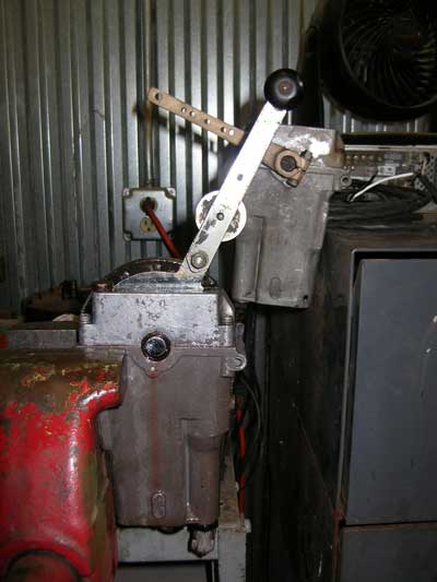
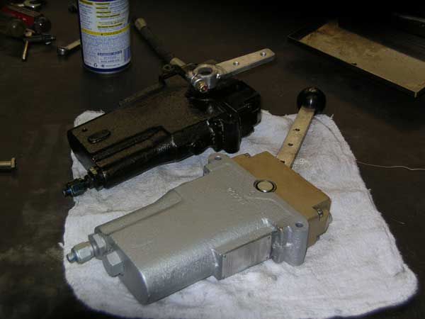
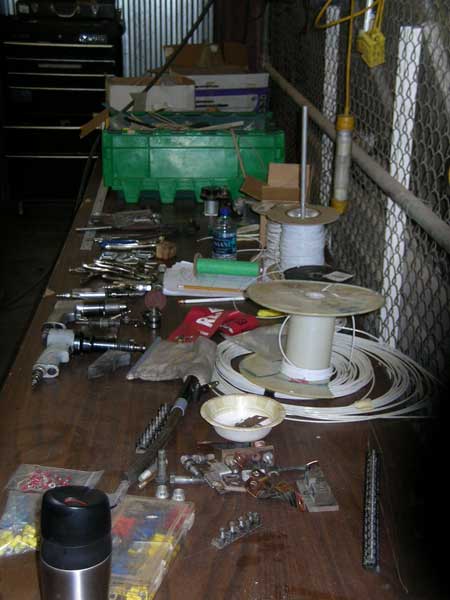
I stopped by Dave's work area a while ago and here is a shot of the finished master and slave for what I think he said was the mixture control on the Testiclese test stand.

Image

Dave is busy sorting parts and tools to go to Addison to help maintain the B-24A at its new base there.

Image

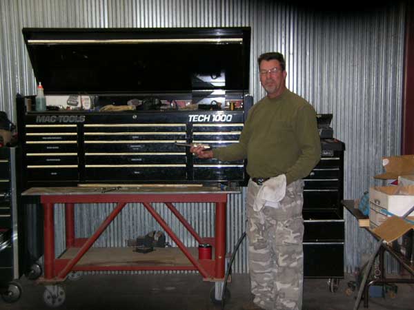
Below, Dave is pulling tools from the main tool chests to go into a smaller one that he will be driving to Addison in a few days.

Image

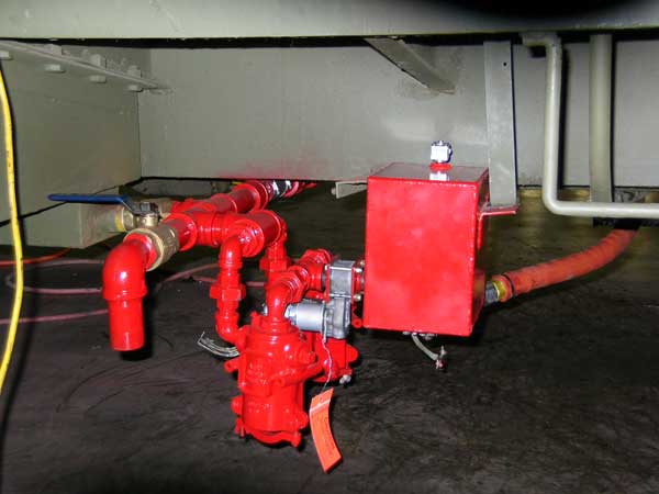
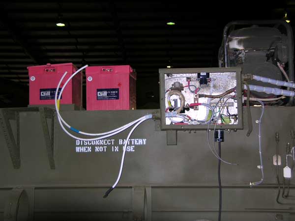
Below is a shot of the fuel filters and pump discussed previously.

Image

All the old wiring from the control cab is being replaced. This is the panel right behind the engine.

Image

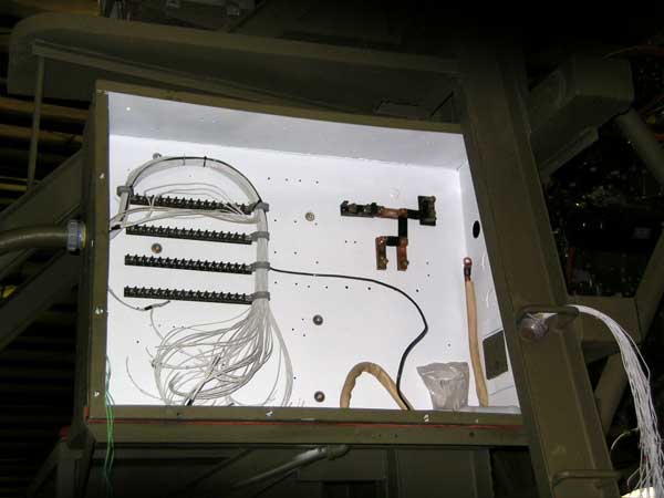
This is part of the wiring for the main power for the test stand.

Image

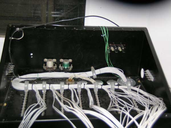
Below is the main console in the cab with the new wiring harness being installed.

Image

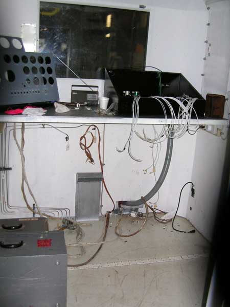
Below is a view of the cab. If I understand Dave correctly, the panel on the left will come out as not being needed. The boxes on the floor contain an engine/ignition analyzer I was told.

Image

A view of the business end of the test stand showing new oil and fuel lines and fittings installed.

Image

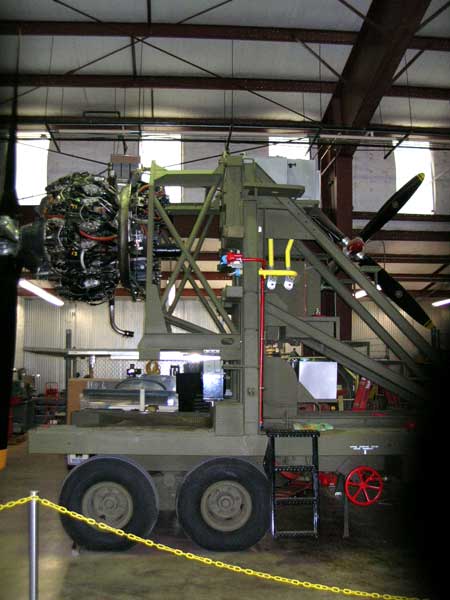
Another view of the test end showing the oil coolers mounted below the engine and also the oil drip pan assembly that can be retracted as needed, I think.

Image

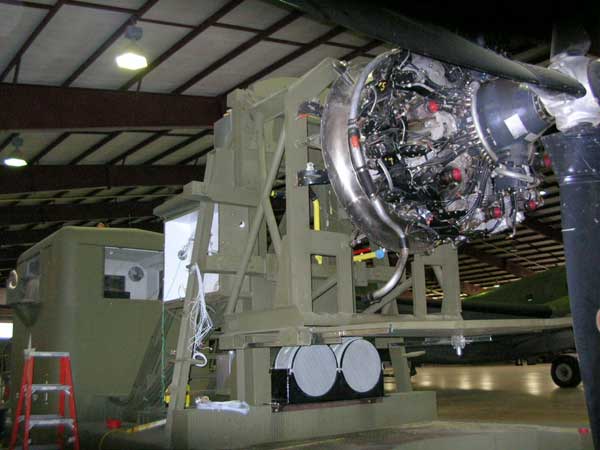
The engine shown is one of FIFI's old R-3350-57 which will basically be used to test the functioning of the test stand. Work on the new hybrid R-3350 engines continues and Dave said he was taking some parts including additional cowling parts to Ezell Aviation on his way to Addison to continue the reworking of the different exhaust manifold and other changes needed to fit the original nacelles.

Hopefully I've provided correct info on all this but if not, Dave is free to correct or add to this when he gets a bit of free time.

Randy


Top
 Profile  
 
Display posts from previous:  Sort by  
Post new topic Reply to topic  [ 1022 posts ]  Go to page Previous  1, 2, 3, 4, 5, 6, 7, 8 ... 69  Next

All times are UTC - 5 hours


Who is online

Users browsing this forum: No registered users and 22 guests


You cannot post new topics in this forum
You cannot reply to topics in this forum
You cannot edit your posts in this forum
You cannot delete your posts in this forum
You cannot post attachments in this forum

Search for:
Jump to:  
Powered by phpBB® Forum Software © phpBB Group