I have volunteered to re-install the original radio stack into the B-24A "Ol' 927" behind the co-pilot's seat. I would like to get some assistance and suggestions from those who know about these radios on where to go from here. I want them to all be at least cosmetically complete but I also want make them operational where possible.
Here are the radios -
No part of the stack (as far as I'm aware) but I'm going to get it re-wired and prepped anyway -
Issues -
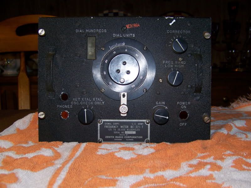
1) The BC-221T is non-operational due to lack of all of the vacuum tubes and a large portion of the wiring. I'm also missing several covering panels and obviously also missing the power switch and the headphone & mic jacks. I am going to get with the Squadron MX Officer to see about wiring up the jacks on the left side with a modern pair and modern wiring to make an additional intercom plug-in, but I need to know what the appropriate power switch is for this radio and if someone has it, please PM me. Also, if anyone is willing to donate a manual on this or any manual to help me, please let me know. If I get a manual, it might make full restoration of these radios possible.
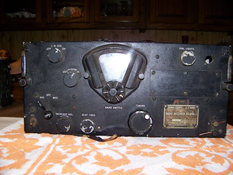
2) The BC-348-J is complete and most likely operational as all of the tubes and mechanics appear to have no defects. However, there is that hole in the upper right corner. Anyone know what is is? I also have my doubts that the switch under the mic connection is correct as the R4D's BC-348-O has a standard 2-wire mic & headset jack pair in that position.
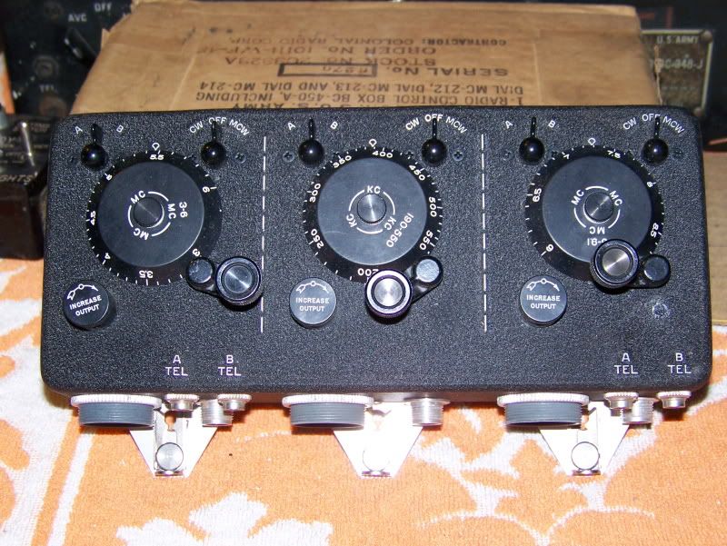
3) The BC-450-A is NOS, so it needs no work, but I need education on what it is and its purpose.
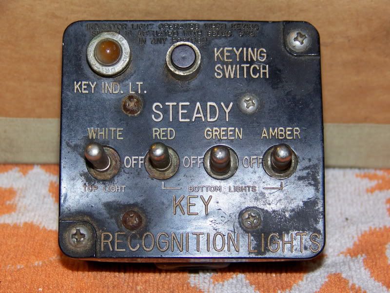
4) The signal box has all of the wires cut so will need to be rewired, but I need to know what gauge of wire is appropriate for this application for me to rewire it. The box is complete, all components appear to be in good working condition, and the bakelite is in pretty good shape, so I think a surface cleaning of the interior will be more than enough. I would like to "rehabilitate" the lettering however if possible, so what is the appropriate paint to do that with? I will probably put a coat of black paint on the box face if the blemishes don't come out on their own as well, so it would be more reason to re-do the pain - that is unless someone has a replacement face or box that is in NOS or near NOS condition that they'd like to donate.
Again if anyone has manuals for any of these units, please let me know. I accept donations or can talk about acquisition if needed. I'm running on a budged of $0 after-all.