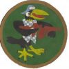
I am not sure you need the 3 rollers....you do, but I would re-examine their proximity and the fact none oppose each other. After I roll formed these hat stringers from .040" 3003-H14 (certainly easier to mar due to softness), I then power rolled them into the semi-circle we need for our cowling.

The caster wheel is levering against the rollers at spindle and as those two fully contain the stringer, there is no profile distortion. The tools are lubed and highly polished H13 steel (lots of chrome so take a good polish). I did have some drag marks, but they were
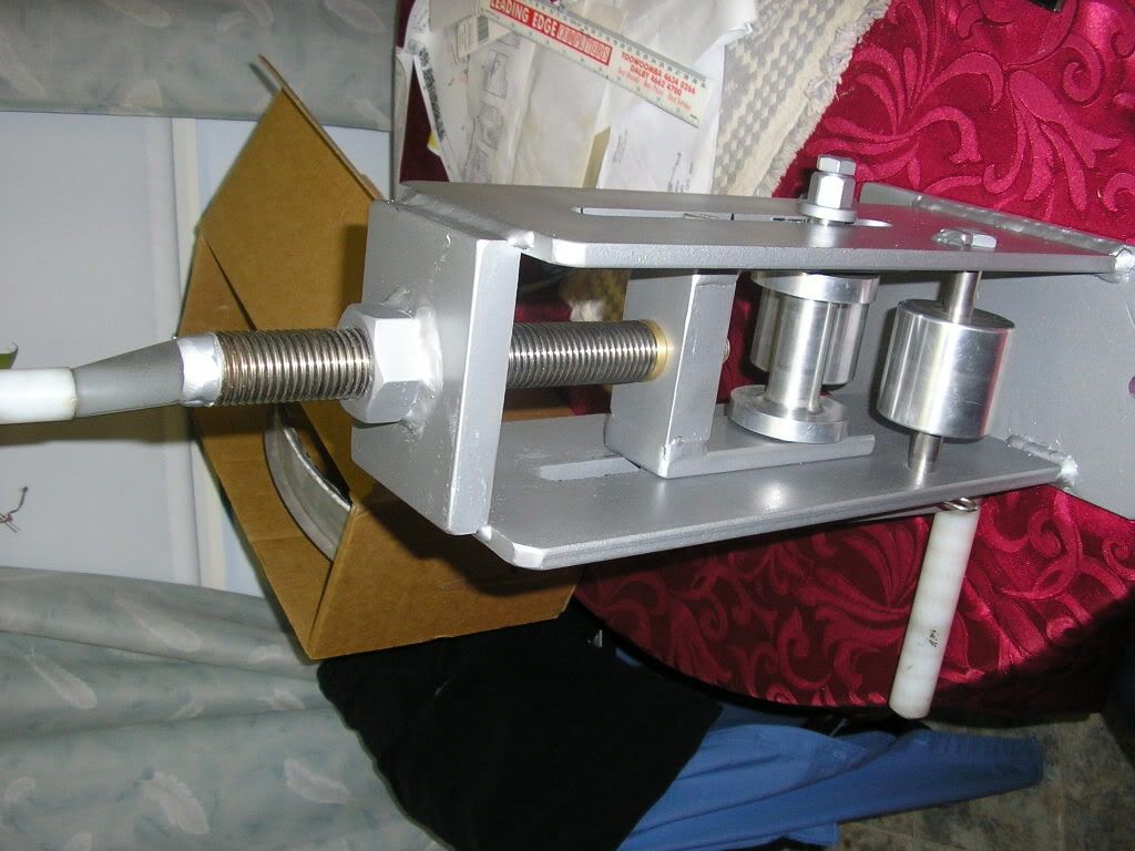
polishable with Scotchbrite. I bumped the caster in to adjust radius. Due to its mechanical avantage it tales little effort.

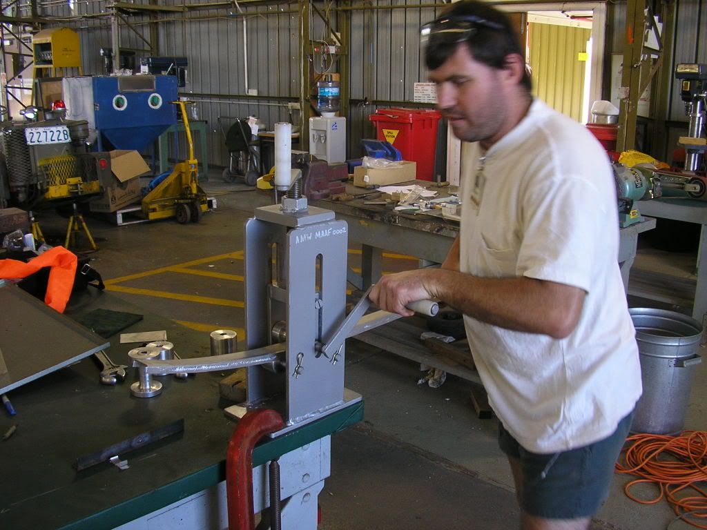
The results we perfect fitment.....

It is holding paper between the stringer and the spinning.....that's mitee close!!

I do not know if this is of any relevance to your project. But I find ideas many times when observing other's work. What I have shown above with a Bridgeport, you can do with a lathe ( I was going to use the lathe, but it is too close to the wall and a 7' stick won't clear!)or horizontal mill if you feel the setup takes more power and rigidity. Just in a perpendicular plane.
Here's the poop to the above set up and possibly your problem......By having a driver and a driven roller directly opposite each other and that have adjustable centers, the power to drive the material is gained by the pressure exerted on the material when closing the center distance....not the pressure from adjusting the radius of arc to be formed as your tool does! This allows you to relieve the rollers to ease scuffing!!!! This allows many light pressure passes which can ease marring. You can have the rollers grip the material on the opposing faces and have plastic flanges. Give it some thought. It may not help your situation but it presents another alternative.


 [/img]