A place where restoration project-type threads can go to avoid falling off the main page in the WIX hangar. Feel free to start threads on Restoration projects and/or warbird maintenance here. Named in memoriam for Gary Austin, a good friend of the site and known as RetroAviation here. He will be sorely missed.
Post a reply

Re: B-17G "Chuckie" Update

Mon Nov 30, 2009 12:05 pm

More excellent images, Paul. I notice that the second antenna is located somewhat at the convenience of the installer. It appears that two different ribs are used from airplane to airplane. Chuckie has the antennae located closer together as on the 487th Group ship:
Image

Sorry about the photo, but you can make out both of our antennae with the propeller blade in between. The second antenna is definitely a modification as the skin cutout has a separate fairing that doesn't fit as cleanly as the original.

Also, I take note of ship 44-8785 being without a top or chin turret. Maybe we'll just let our nose alone! :wink:

THAT SHOT OF THE TRAPEZE IS AWESOME!!!!!!!!!!!!


Scott

Re: B-17G "Chuckie" Update

Mon Nov 30, 2009 2:07 pm

Second Air Force wrote:I take note of ship 44-8785 being without a top or chin turret. Maybe we'll just let our nose alone! :wink:


When the 305th and 306th Bomb Groups' PFF B-17s were retained in Europe for Project Casey Jones at the end of the war, the armament was removed as it was no longer required.

Glad you liked the trapeze photo, I was scanning through a series of thumbnail images when it caught my eye. :D
Hopefully it will help with figuring out the reproduction.

(And if my last image in the Mickey thread is anything to go by, you might be making two sets. :lol: )

TTFN,
PB

Re: B-17G "Chuckie" Update

Mon Nov 30, 2009 2:22 pm

RAMC181 wrote:
Second Air Force wrote:I take note of ship 44-8785 being without a top or chin turret. Maybe we'll just let our nose alone! :wink:


When the 305th and 306th Bomb Groups' PFF B-17s were retained in Europe for Project Casey Jones at the end of the war, the armament was removed as it was no longer required.

Glad you liked the trapeze photo, I was scanning through a series of thumbnail images when it caught my eye. :D
Hopefully it will help with figuring out the reproduction.

(And if my last image in the Mickey thread is anything to go by, you might be making two sets. :lol: )

TTFN,
PB


Paul,

Good eye on City of Savannah! I'll be absolutely certain to keep record of all my construction measurements--in fact, I may just have to contact them before I get started. Two is almost as easy as one!

You've opened another can of worms with those B-24 photos. I'd always been told over the years before I really started researching H2X that both the Lib and Fort used a '24 hydraulic turret stanchion. Now I see (and found it in an operator's manual that I have acquired) that they both used the hand crank trapeze. If you notice the jackscrews in the interior photo are partly down, matching the external photo. Great stuff!!!!!

Scott

Re: B-17G "Chuckie" Update

Mon Nov 30, 2009 8:13 pm

Paul,
The next time I'm in the UK or you're in the States, the pints are on me! :drinkers: :D

Re: B-17G "Chuckie" Update

Tue Dec 01, 2009 12:27 pm

Try not to make the dome just yet, give me a month to see how negotiations go on the original.

Re: B-17G "Chuckie" Update

Tue Dec 01, 2009 12:56 pm

PMs sent, Fortress Fan.

Re: B-17G "Chuckie" Update

Tue Dec 01, 2009 2:29 pm

Current state of the 3D scanner assembly model, built using the "TLAR" method. :wink:

Image

TTFN,
PB

Re: B-17G "Chuckie" Update

Wed Dec 02, 2009 3:01 pm

I was sent this photo today.
Although not of the greatest quality, it does show the trapeze and radome top plate with it's associated bracketry quite well.
Note it's fully extended and there is no modulator or other equipment bolted into the racks. The floor support framing shows up well too.

Image

The 78xx contract number on the radio room bulkhead puts it in the 44-8401 to 44-8500 serial bracket (B-17G-65-VE)

All the best,
PB

Re: B-17G "Chuckie" Update

Wed Dec 02, 2009 11:26 pm

I'm guessing that last photo would have been taken of an airplane either being stripped after the end of hostilities or in for major repairs. Regardless, it shows more details such as the support structure aft of the radome itself. The flooring to the left of the radome is interesting as well, being somewhat different than some of the other photos you've discovered. The more I study the radome installation, the less standardized the flooring and equipment placement seems to be. That photo is of an airplane in the block just ahead of ours, making me think I should start drawing up more diagrams.

Scott

Re: The "Chuckie" twin antenna mystery continues

Tue Dec 08, 2009 2:20 pm

RAMC181 wrote:Further to my finding this photo showing a PFF B-17G with twin antenna masts on the fin:

Image

I've found two more examples, albeit on "Casey Jones" aircraft in the 45-46 period.
In both cases the additional mast is the aft of the two.

B-17G-80-VE 44-8785, originally "Crack Up" of the 457th Bomb Group at Glatton before being transferred to the 305BG on May 23rd, 1945.
Wartime photos of this aircraft show no additional mast installed.

Image

B-17G-80-VE 44-8796 KY-F "Laura" of the 305th Bomb Group.

Image

Both images are from Robert Hutson's collection of photo's belonging to his late Grandfather Norman LeRoy Hutson Sr., who was with the 305BG during Project Casey Jones.

All the best,
PB


I shot a few photos of our antenna set-up Sunday. The aft antenna is our "original" one--notice the nice fairing on it versus the flat sheet that was bent to fit the forward one:
Image

Here is the mounting inside the fin. The first photo is of the factory installed antenna. This one is fastened firmly to a dorsal fin rib and blocked at the front end to keep it firmly in place:
Image

This is the forward mount. The installer didn't tie it to the rib forward of it, and it moves around quite a bit. Definitely installed later and with less engineering than the original.
Image

I spent a bunch of time working on measurements of the radome trapeze and radio room installations. Here is my "drafting desk" in the radio room.......... :rolleyes:
Image

Scott

Re: B-17G "Chuckie" Update

Sat Dec 12, 2009 1:36 am

Paul (RAMC181) has been providing us with many fantastic wartime photos of the H2X equipment that we are planning to reinstall in Chuckie. He has consented to let me use the USAAF photos so that I can show everyone where we're starting from and where we want to end up.

Here is comparison #1, the right side of the radio room. First is our radio compartment. It is a bit hard to see from the photo, but when I studied the wartime photos and compared them to the existing holes drilled in the structure of '543, I was able to locate where the bracketry was bolted on when the radar set was installed.
Image

Next is the fully equipped wartime version:
Image
The little yellow arrow is pointing at the window buried in all of that radar equipment. Notice also that the normal B-17 radio equipment is located on the bulkhead racks and that all the H2X boxes mount immediately behind them. The Signal Section mechanics must have frowned on the way this setup was installed......

So, this gives a little idea of the front part of the radar operator's station and the amount of equipment we will need to source and install.

More later,
Scott

Re: B-17G "Chuckie" Update

Sun Dec 13, 2009 7:30 pm

For those of you that have been following the Pathfinder saga, I've finally decided on how to build a mold for laying up a new radome. I mentioned a few posts ago that I'd thought styrofoam would be a logical (and relatively inexpensive) material to construct the male mold from. After pricing large blocks and balls of styrofoam I decided to find another way. That stuff is EXPENSIVE when you need a four foot by three foot block of it. After trading ideas with Cozmo I changed my plan a bit, to a material that is easy to work with and cheaper. An unairworthy four-by-twelve sheet of 2024T3 just happened to be available in our hangar, so aluminum it shall be.

Pretty simple after deciding what to use. I'll just cut a few circular pieces of plywood the correct diameter to act as former rings and wrap the sheet around them. Then, just rivet the seam together and secure the skin to the former rings. The domed part of the form hasn't been purchased yet, but I'll be sure to fill you in when I am sure my idea will work. After finishing the form I'll lay up the fiberglass that will be the actual radome. When the fiberglass cures the mold will be removed. I hope it works as easily as it sounds........... :rolleyes:

Here's a photo of the body of the mandrel after I formed it into the correct diameter. The actual body of the radome will be about six inches less than the overall height shown here. Ellen and Mickey posed with it to give an idea of the size of the thing:
Image
I'm gonna need a lot of fiberglass cloth and resin!

Scott

Re: B-17G "Chuckie" Update

Sun Dec 13, 2009 7:56 pm

Hi Scott,
I have 2 or 3 rolls of fiberglass cloth. Some fine and some coarse weave that you guys can have if the shipping can be taken care of.

Take Care,
David

Re: B-17G "Chuckie" Update

Sun Dec 13, 2009 8:03 pm

Regarding shipping Fiberglass cloth, etc. email me a tonnage, size and your 'from' address and I'll see if my Fedex account will take care of it.

Scott would you email me where you would want it sent? I presume to your home?

Re: B-17G "Chuckie" Update

Sun Dec 13, 2009 10:54 pm

Thanks for the offer, David!

Hawkeye, email sent.

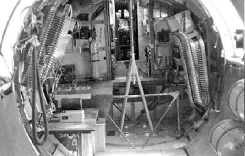
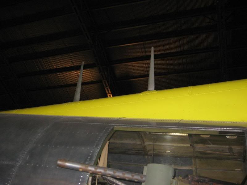
Everyone else, here is another radio room comparison. I posted "before and after" photos of the front portion of the radar operator's station a little while ago. This post will pertain to the aft right corner of the radio room. First, a photo of our bare compartment:
Image

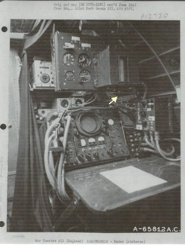
Next is a photo of the configuration I'm planning for our airplane, courtesy of Paul once again:
Image

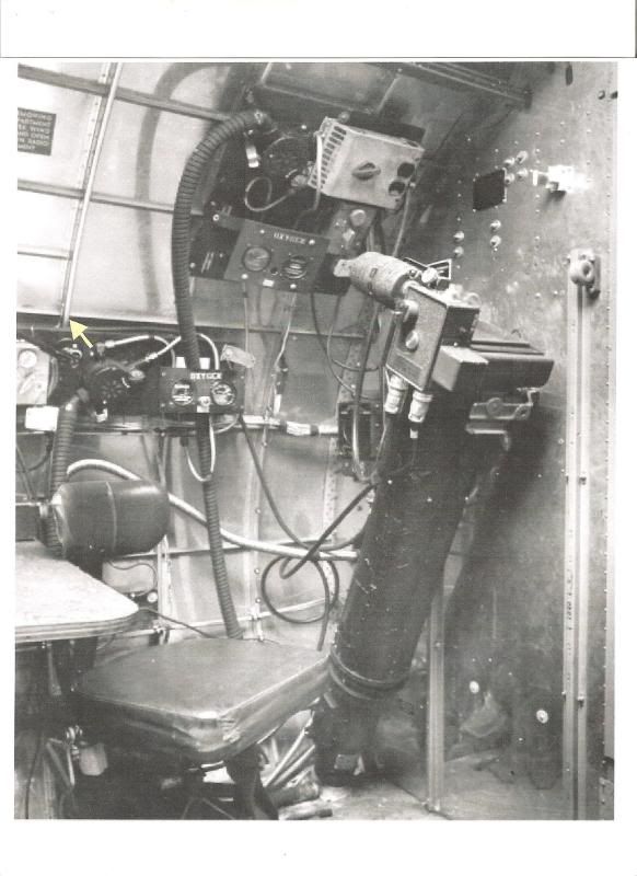
The first thing that jumps out at you is that big monster of a camera stowed on the aft wall. The idea was to place the lens tube onto the radar screen and shoot photos of the radar display during a strike. There were several different configurations used here, including one where three of the original liason transmitter tuning units were still mounted on the aft wall. In this instance you can see the vertical radio support channels still installed even though the black boxes have been moved.

Once again, I was able to locate empty holes in the frames on our airplane in the exact location of all the equipment on the sidewall. To properly locate everything, I used the former ring with terminating stringers as my guide. Just above the oxygen regulator is a yellow arrow indicating out my reference point. Our airplane matches perfectly, something I'd hoped for but didn't really expect to happen.

If you look closely at the modern-day photo you will see a small bit of black tape on the floorboard aft of the seat. This is the approximate location of the radar operator's seat once the scope and desk are installed. I'll be hunting for the correct seat once we get started with the radio room refurbishment.

Scott
Post a reply