A place where restoration project-type threads can go to avoid falling off the main page in the WIX hangar. Feel free to start threads on Restoration projects and/or warbird maintenance here. Named in memoriam for Gary Austin, a good friend of the site and known as RetroAviation here. He will be sorely missed.
Post a reply

Re: B-17G "Chuckie" Update

Mon Dec 14, 2009 6:36 pm

How are you going to lay the fiberglass in such a deep "barrel?

Re: B-17G "Chuckie" Update

Tue Dec 15, 2009 1:36 am

Django,

I'm going to lay the fiberglass on the outside of the form. I looked at a female mold but didn't know how I'd lay the material in that big pit. I thought about a two piece dome also but I think the male mold will work best. I'd prefer to keep it one piece as the original was built. One nice thing about this project is that the surface of the original radomes wasn't perfectly smooth. It has a small bit of "texture" to it that will be easy to replicate if I apply the gelcoat correctly. I plan to build a much smaller prototype first to proof the idea.

Scott

Re: B-17G "Chuckie" Update

Mon Dec 21, 2009 2:36 pm

Here's a quick radome form/homework update. I picked up some plywood, cut it to the correct diameter, and stuffed it inside. Then it was a simple task to tighten the tie-downs to secure the metal and drill holes along the seam. Next I'll rivet the whole thing together and prepare to build the domed part.
Image

Image

Scott

Re: B-17G "Chuckie" Update

Sun Dec 27, 2009 4:54 pm

This AM-19/APA-14 Torque Amp for the H2X rig is advertised for sale in the Netherlands...........

Image

TTFN,
PB

Re: B-17G "Chuckie" Update

Sun Dec 27, 2009 8:22 pm

Paul,
PM sent.

Re: B-17G "Chuckie" Update

Mon Dec 28, 2009 11:04 pm

Paul posted several photos of the lower wing antenna installations on PFF Fortresses on the Photo Gallery thread. I'm going to take the liberty of re-posting one of them here. The four arrows under the wing are pointing to the SCR 718 Radar Altimeter antenna installation.
Image

Well, Paul, here is the evidence. I shot these three photos this evening of the right wing of Chuckie. It turns out that she had the twinned antenna layout on each wing. Steve Swift assisting with the gloved hand, shooting inboard:
Image

The leading edge of the wing is toward the bottom of this photo. Notice that there are three screws above and below each little plate. These are the screws fixing the inner doubler to the skin to reinforce the area.
Image

We pulled one of the cover plates off to study what was under it, and a nice antenna coax cable hole emerged:
Image

The more stuff Paul unearths with his research, the more correlations we find on '543. She seems to have gotten all the bells and whistles when she was converted to a PFF ship.

Scott

Re: B-17G "Chuckie" Update

Tue Dec 29, 2009 10:35 pm

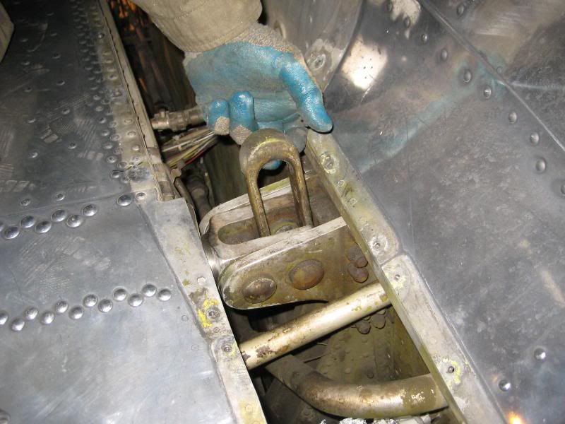
Ok, so I'll try to do a quick update on what we've been working on lately on the B-17. Our main focus has been towards completing the spar A.D. and good news to report - we have removed half of the necessary bolts, and had the NDT (Non Destructive Testing) guy out today to do the Eddy Current inspection and no cracks or other defects were found! 8) Many thanks to Eric Shaw of Apex Inspections in Carrollton, TX for helping us out with that. I highly recommend him if you ever need any NDT done. Contact me if you need his info, he is very warbird friendly.

Now we have to replace those bolts that we took out with new ones and then remove the other half of the bolts and repeat the NDT inspection on those. Got that? :? :wink: Once that is done, then we can replace those bolts and then reinstall the inboard fuel nacelles and check off a HUGE checkbox on the list to getting her airborne again.

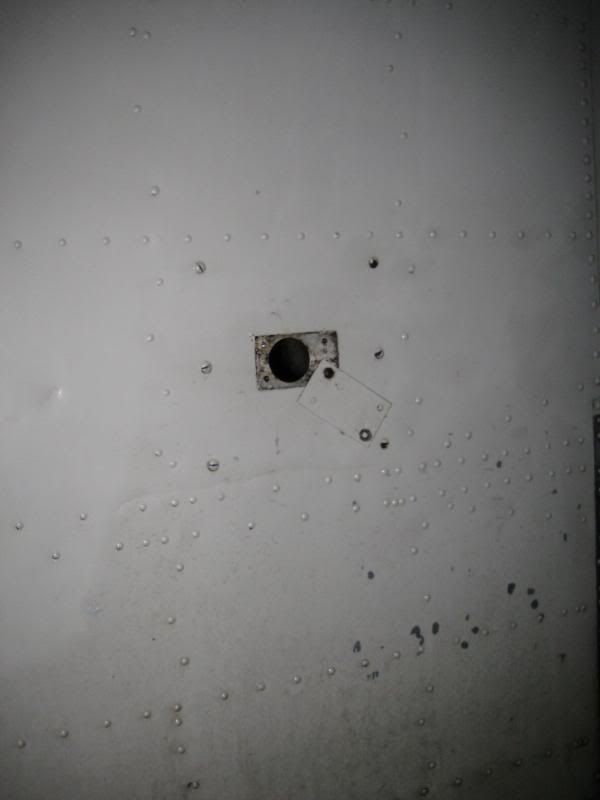
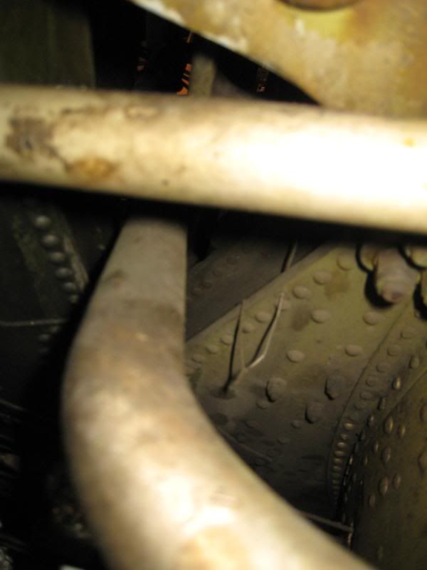
While we were in the area, I made the mistake of looking around inside the wing and found a small pocket in the #1 rib brace that had filled up with debris over the last 65 years. Well guess what, pockets filled with debris + 65 years = corrosion.

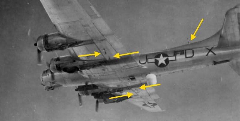
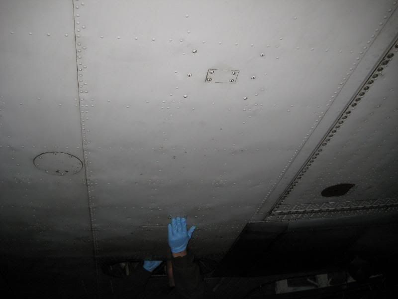
Here's the offending area, just forward of the RH aft lower spar terminal pin.
Image

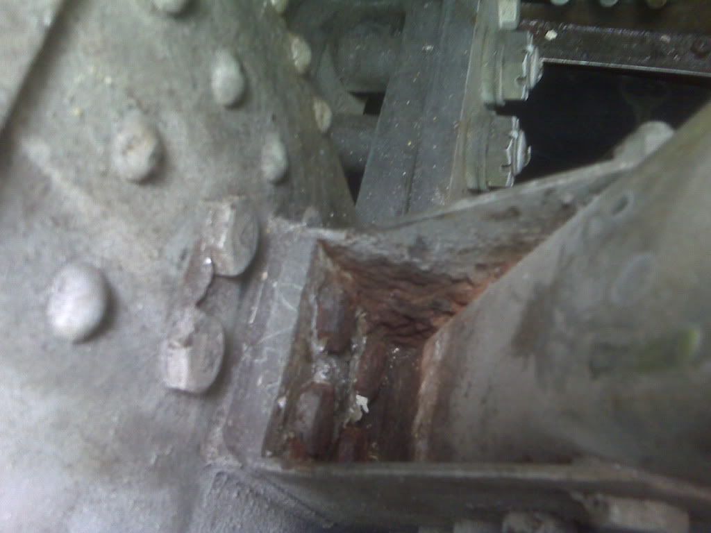
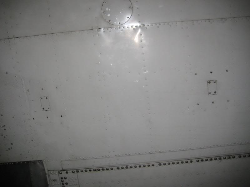
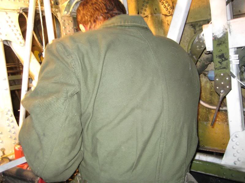
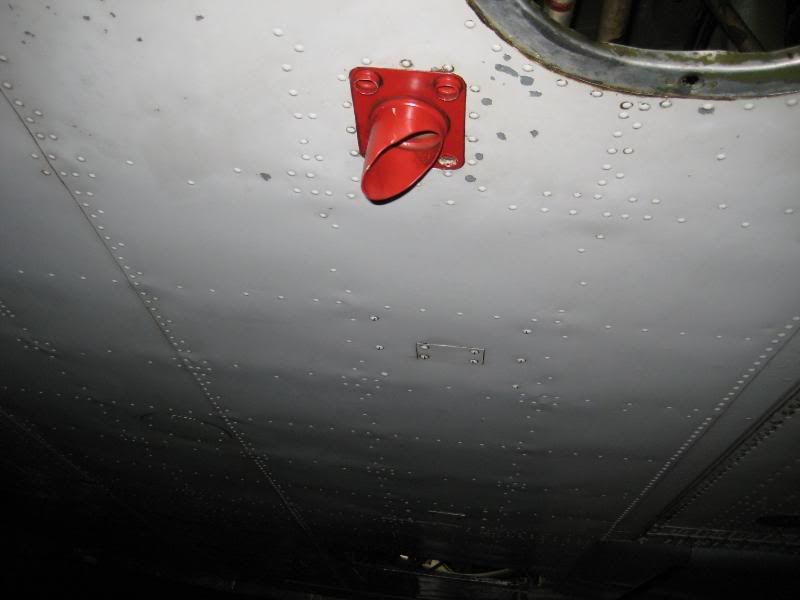
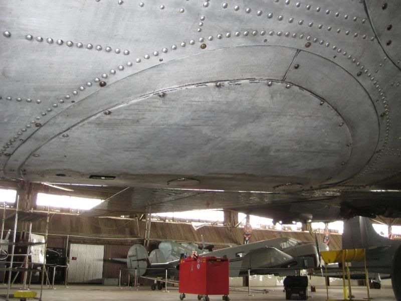
Another view of the area after Scott started to remove the diagonal brace to gain access to the "U" channel an doubler that is corroded.
Image

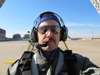
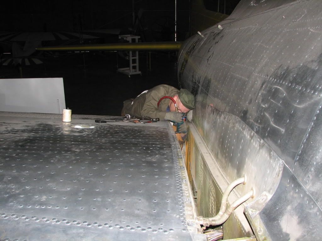
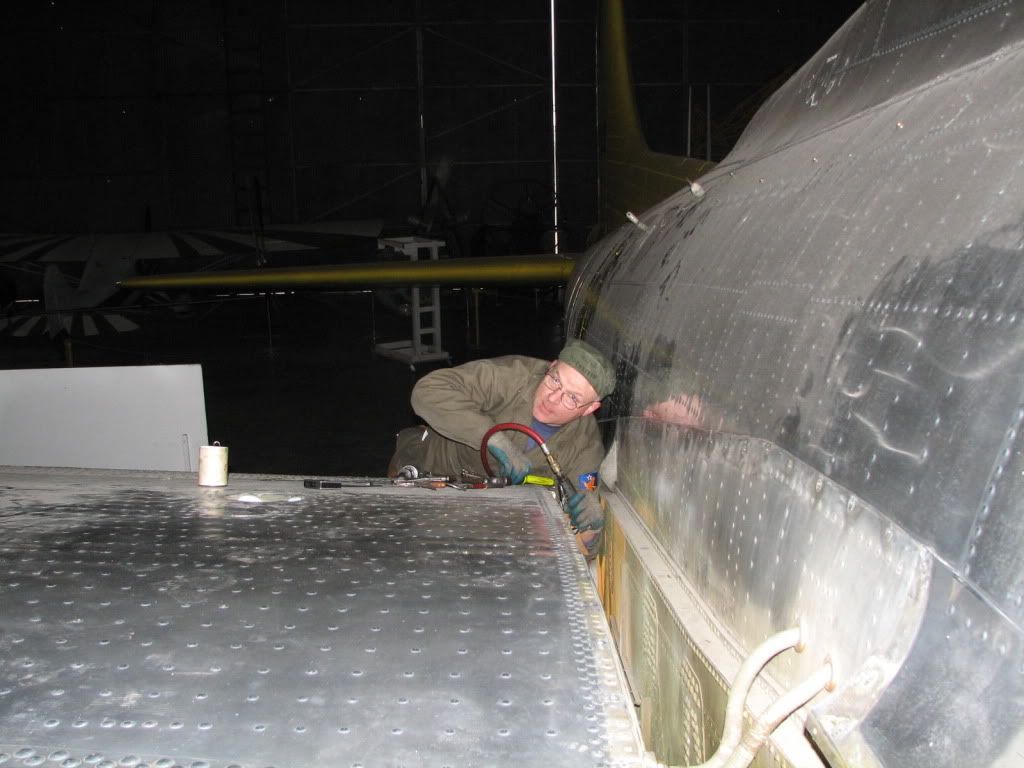
Here's Scott, complete with HBT coveralls and hat, (yes, he works in them) working on drilling out the big ol' ice box rivets that held the brace in.
Image
Image

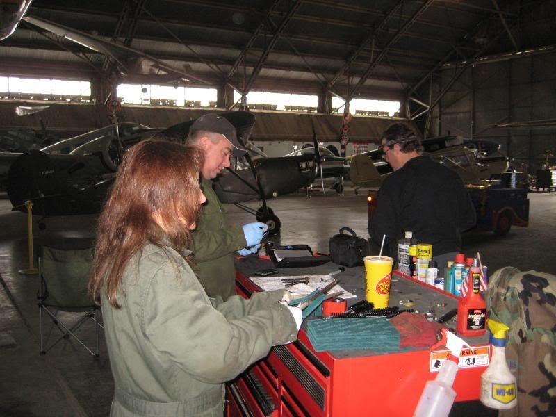
Many thanks to Scott and Ellen, Steve Swift, Mike Tolfa and Pat Mahaffey for bearing the cold this week to help work on the old girl. It was in the upper 30's and snowing at Meacham today and that old B-29 hangar isn't heated so it just acts like an ice box!

We're working just about every day this week on the B-17 since we're off from our paying jobs - this is our REAL job. We hope to be flying early next year in time to get our maintenance flights doneand get our crews recurrent in time to make it to Altus and then T.O.M..

We'll post more as the week progresses I'm sure.

Re: B-17G "Chuckie" Update

Wed Dec 30, 2009 6:43 am

Many thanks for the latest update CrewDawg ( and for all the previous ones too ! )

Best wishes to you and your team and "Chuckie" for 2010

Re: B-17G "Chuckie" Update

Wed Dec 30, 2009 9:51 am

Here's another mini-update on yesterday. As Bill said, it wasn't the warmest in the hangar, but then again, we weren't sweating in 105 degree Texas summer, either. I was thinking as the day went on that the conditions weren't all that different from England (for those mechanics lucky enough to work in a T2 hangar) during the winter months.

Here are a couple of photos of the rest of the group toiling away--we didn't get a picture of Mike as he was on the computer and telephone chasing parts:

Steve working on removing the corroded gusset bracket:
Image

Ellen prepping scotchbrite for some cleaning projects, Bill measuring hardware, and Pat heading back to his tasks:
Image

We found another neat little detail on the airframe that might be of interest. This lifting loop is connected to the taper pins that attach the upper forward spar fittings. These were used to hoist the airplane from place to place in the factory after the wing-to-body join and then simply safety wired to the structure. The first photo is of the loop and the second one is of the WWII Vega-issued safety wire on the fuselage web.
Image
Image

Scott

Re: B-17G "Chuckie" Update

Wed Dec 30, 2009 9:18 pm

Here are a couple of photos of ETB-17G s/n 44-8543 while on bailment to Federal Telecommunications Corporation at Teterboro, New Jersey. The photos were allegedly taken in 1957. Note the interesting wingtip antennas! In fact, there are many "non B-17 standard" antennas on the ship in these shots, and few "B-17 standard" ones. I have huge scans of these two photographs (done at 600 dpi) on my hard drive. Looking at them enlarged, I can see many interesting antennas. There are no masts installed on the vertical fin spine, although in the huge scan, the fairing where the "standard" one should be installed can be seen. Also visible in the huge scan are two long wire antennas extending from two different points on top of the fuselage to two different end points on the vertical fin. The longer of these, which terminates at the "normal" wire antenna endpoint on the vertical fin, has an insulator in the middle which implies that its entire length is not electrically active. This antenna appears to begin just forward of the radio compartment top hatch. The second wire antenna runs from an insulator on the fin spine, just forward of the gunner's window, to a point about 2 - 3 feet below the other wire antenna on the fin. There is an additional wire antenna installed between two masts on top of the center section. There is a short, thick antenna mast just behind the radio compartment top hatch; it does not appear to support any kind of wire antenna. There's an extra ADF "football" above the flight deck. Underneath the fuselage, there is another short, thick antenna with a wide, conical base. It's visible in the first photo below, just behind the left main gear tire, and in the second photo, behind the right main gear tire. There are several very short, stubby antennas installed on the belly, about where the ball turret would normally be. All of this is probably boring to most of you, but for a "radio guy" like me, it's interesting stuff! :rolleyes:

Image

Image

Re: B-17G "Chuckie" Update

Wed Dec 30, 2009 9:54 pm

Ta Dean,

Your second photo shows the underwing radar altimeter antennae well, along with the as-yet unidentified "lump" close to the outboard one that appears on most wartime installation pictures.

TTFN,
PB

Re: B-17G "Chuckie" Update

Thu Dec 31, 2009 10:03 pm

Dean,
Great shots! Thanks for posting them. That explains all of the patches and holes on the belly that we've often wondered about. Lately we tend to be more focused on her days as a Pathfinder and forget about her duty with the FTC.

Paul,
Scott shot some pictures of the unidentfied lump in question today and will probalby be posting them with the explanation in the very near future.

Cheers and Happy New Year!

Re: B-17G "Chuckie" Update

Thu Dec 31, 2009 11:09 pm

RAMC181 wrote:Ta Dean,

Your second photo shows the underwing radar altimeter antennae well, along with the as-yet unidentified "lump" close to the outboard one that appears on most wartime installation pictures.

TTFN,
PB


Paul, I think this is the unidentified lump you mentioned:

Image

This is the vent for the fuel system. The large angled tube connects to two vent hoses, one to each main tank. The four smaller openings are connected to various other overboard tubes.

Scott

Re: B-17G "Chuckie" Update

Fri Jan 01, 2010 10:03 am

Ta Scott,

I kept seeing a "something" in the wartime photos adjacent to the antennae and wondered it it was related.

TTFN,
PB

Re: B-17G "Chuckie" Update

Fri Jan 01, 2010 10:48 am

k5dh wrote:Here are a couple of photos of ETB-17G s/n 44-8543 while on bailment to Federal Telecommunications Corporation at Teterboro, New Jersey. The photos were allegedly taken in 1957. Note the interesting wingtip antennas! In fact, there are many "non B-17 standard" antennas on the ship in these shots, and few "B-17 standard" ones. I have huge scans of these two photographs (done at 600 dpi) on my hard drive. Looking at them enlarged, I can see many interesting antennas. There are no masts installed on the vertical fin spine, although in the huge scan, the fairing where the "standard" one should be installed can be seen. Also visible in the huge scan are two long wire antennas extending from two different points on top of the fuselage to two different end points on the vertical fin. The longer of these, which terminates at the "normal" wire antenna endpoint on the vertical fin, has an insulator in the middle which implies that its entire length is not electrically active. This antenna appears to begin just forward of the radio compartment top hatch. The second wire antenna runs from an insulator on the fin spine, just forward of the gunner's window, to a point about 2 - 3 feet below the other wire antenna on the fin. There is an additional wire antenna installed between two masts on top of the center section. There is a short, thick antenna mast just behind the radio compartment top hatch; it does not appear to support any kind of wire antenna. There's an extra ADF "football" above the flight deck. Underneath the fuselage, there is another short, thick antenna with a wide, conical base. It's visible in the first photo below, just behind the left main gear tire, and in the second photo, behind the right main gear tire. There are several very short, stubby antennas installed on the belly, about where the ball turret would normally be. All of this is probably boring to most of you, but for a "radio guy" like me, it's interesting stuff! :rolleyes:

Image

Image


To add a little to Dean's observations, here is the radome plug with three cover plates where the small antennae were located:
Image

Scott
Post a reply