SBD-5 Dauntless radio equipment - help!!
Sun Mar 29, 2015 9:17 am
Hi guys - I need some help! I am building a large scale SBD-3 Dauntless (to be converted to, and finished as a French Navy SBD-5 circa 1947)
For those of you who are model makers, this is the 1/18 scale Merit (Trumpeter) kit. From what I understand, the Merit kit is a scaled up version of the old Accurate Miniatures 1/48 kit, the details of which are based on SBD-3 06508 which is found at the National WWII Museum in New Orleans.
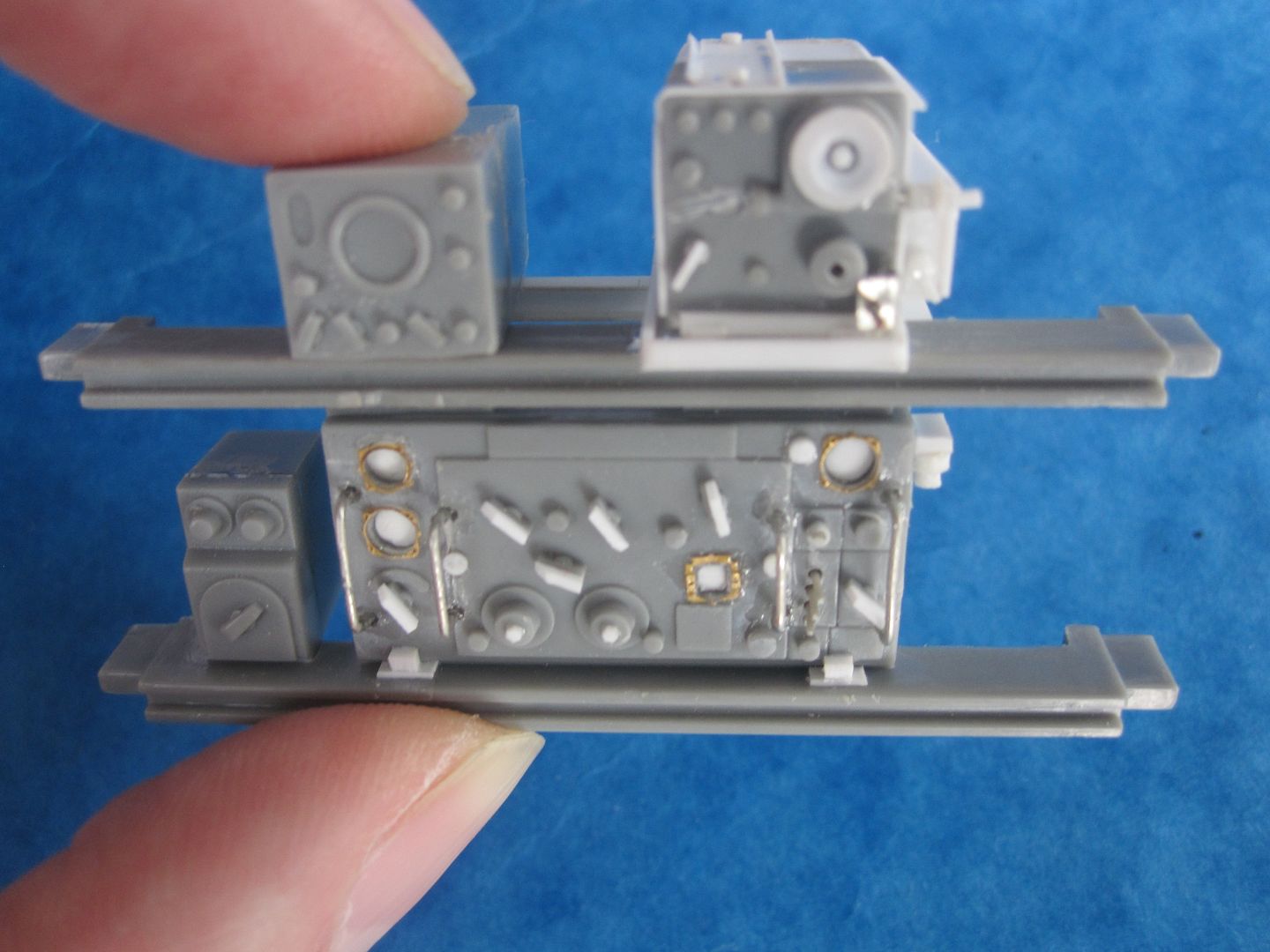
My question concerns the Radio and other avionics equipment. The two photos show the kit parts ‘out of the box’ and also after I have started to add some detail to the parts. I need to identify some of what I’m looking at (one or two I have figured out)
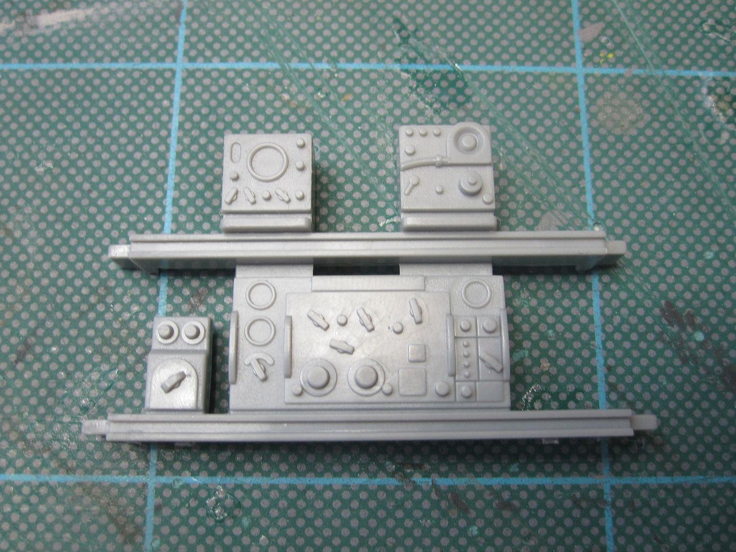
So from top left to top right
RADAR - but what kind is it?
Naval Air Factory RU-19 Receiver with Dual Band Tuning Unit (or is it an RU-5?)
Bottom left to right
Unknown?
Possibly a Naval Air Factory GP-3 Radio Transmitter?
The official aircraft manual states that:
‘The radio equipment consists of an AN/ARC-5 multiple-channel communication radio, a navigation receiver, an ARB receiver, a tactical radio (RADAR), an identification radio and an interphone system’
I am somewhat confused. Does this refer to earlier SBD-3 models?
If anyone could clarify exactly what I need to replicate, that would be great. Designations of parts / equipment most welcome, as I can then simply google it to find images. I probably need to add some other units - but what? I imagine the restored birds don't have the full compliment of equipment
cheers,
Rich
For those of you who are model makers, this is the 1/18 scale Merit (Trumpeter) kit. From what I understand, the Merit kit is a scaled up version of the old Accurate Miniatures 1/48 kit, the details of which are based on SBD-3 06508 which is found at the National WWII Museum in New Orleans.
My question concerns the Radio and other avionics equipment. The two photos show the kit parts ‘out of the box’ and also after I have started to add some detail to the parts. I need to identify some of what I’m looking at (one or two I have figured out)
So from top left to top right
RADAR - but what kind is it?
Naval Air Factory RU-19 Receiver with Dual Band Tuning Unit (or is it an RU-5?)
Bottom left to right
Unknown?
Possibly a Naval Air Factory GP-3 Radio Transmitter?
The official aircraft manual states that:
‘The radio equipment consists of an AN/ARC-5 multiple-channel communication radio, a navigation receiver, an ARB receiver, a tactical radio (RADAR), an identification radio and an interphone system’
I am somewhat confused. Does this refer to earlier SBD-3 models?
If anyone could clarify exactly what I need to replicate, that would be great. Designations of parts / equipment most welcome, as I can then simply google it to find images. I probably need to add some other units - but what? I imagine the restored birds don't have the full compliment of equipment
cheers,
Rich
Re: SBD-5 Dauntless radio equipment - help!!
Sun Mar 29, 2015 8:59 pm
I know exactly what both the ARC-5 and ARB radios look like and your provided plastic pieces do not fit either one. I donated my ARB radio and associated RDF-1A loop antenna to the Moffett Field (CA) Museum a few years ago. The ARB was used in quite a variety of navy aircraft (e.g. PBY, PV, TBM, SO3C, et.al.). I believe that the ARC radios were could be found in nearly military aircraft produced in the USA during WWII! The ARB at Moffett remains on display there.
www.fuselagecodes.com
www.fuselagecodes.com
Re: SBD-5 Dauntless radio equipment - help!!
Sun Mar 29, 2015 10:50 pm
Hi Rick,
The plastic bits in your pic are correct for an SBD-3 radio installation (GP-7 transmitter, RU-19 receiver)
SBD-5 used AN/ARC-5 radio installation - a very different radio setup than SBD-3
Check out SBD-5 POH page 30 for a pic of the ARC-5 radio install. Lots more boxes than -3 radio setup.
Link to SBD-5 POH below - scroll down to page 30 in the preview to see the radio install pic
https://books.google.com/books?isbn=1430317493
Hope that helps,
Dewayne
Re: SBD-5 Dauntless radio equipment - help!!
Mon Mar 30, 2015 5:09 pm
Lower left is the antenna loading unit for the GP-7 transmitter (see attached). Upper left has managed to evade my reference material. -Adrian
et.com/user/omega7/media/GP%20antenna%20loading.jpg.html]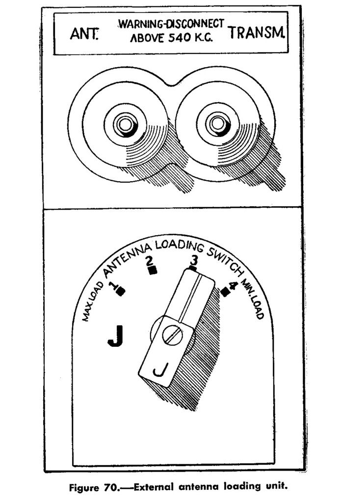 [/URL]
et.com/user/omega7/media/GP%20antenna%20loading.jpg.html]
[/URL]
Re: SBD-5 Dauntless radio equipment - help!!
Mon Mar 30, 2015 10:23 pm
Upper left is a model of an LM frequency meter.
The LM input was connected to a terminal labeled CFI (crystal freq indicator) on the GP-7 and was used to accurately measure the transmitter's output frequency.
A unique calibration book specfic to each LM meter was stored underneath it. The operator would dial up a frequency on the LM using the book and then zero-beat the GP-7 to determine what frequency it was transmitting on. There is an output mode switch on the GP-7 that is set to the tune position while doing this so no power is actually transmitted while zero-beating. The GP-7 has a little chart on the tuning unit that the operator could write down the frequency and the various knob positions to tune to it. Each knob or dial on the tuning unit has a letter (A, B, C ,D etc) engraved on it to reference it on the chart. Once tuned to the desired frequency, the output mode could selected from tune to 1/4 , 1/2, or full power to put it on the air.
More info here on the LM frequency meter.
http://www.pa3esy.nl/military/us/meet/LM20/html/lm20-gb_set.html