sdennison wrote:
Did all that spent brass come out of it as well?

Seriously, I'd love to know the engineering behind that design. Many times, restrictors like those were meant to slow the water/coolant flow to give time to get the heat transferred from the engine to the coolant. These are pretty intricate shapes.
Hi Scott,
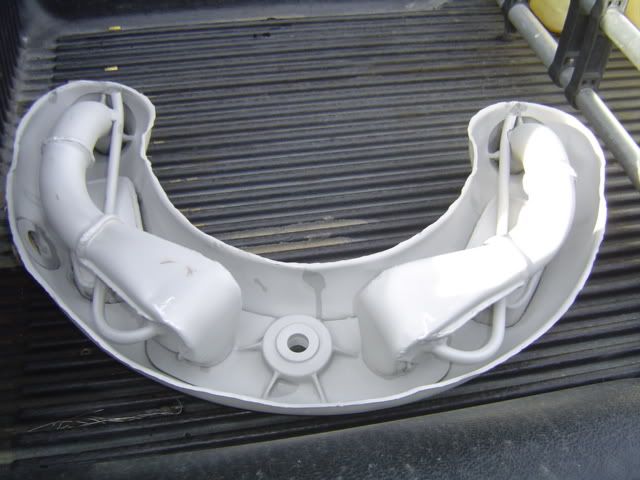
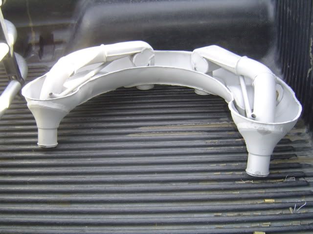
The coolant enters the tank at the top (The two connections in the welded in casting). If you look at the second picture you can see the tube turns into a barrel shape and the small line is welded to the top of the barrel shape. That's a swirl chamber to removed trapped gases and vapor from the coolant. The gases exit through the little tube which is routed to the bottom of the tank so it can pick up coolant and add it to the coolant stream as needed. When properly filled the tank holds two football shaped “pockets” of coolant with open expansion space at the top.
For the B, C models there were two nearly identical versions of these tanks. This is the later version, used on the later B and C and all D, K models which is a little better than the early tanks.
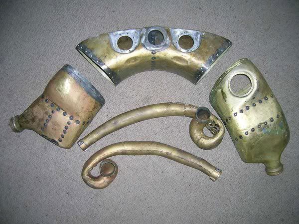
The repairs being carried out on this tank are common! The good news is new built units can now be purchased so an option other than the labor intensive repairs is available.
Jack Roush makes a flow straightener (Not a restrictor) that inserts into the inlets. If the alignment is poor between the bank's outlet spout and header tank inlet (Which it often is), the swirl chamber is a lot less effective. The straighteners are designed to clean up the flow to increase the chamber's efficiency.
John