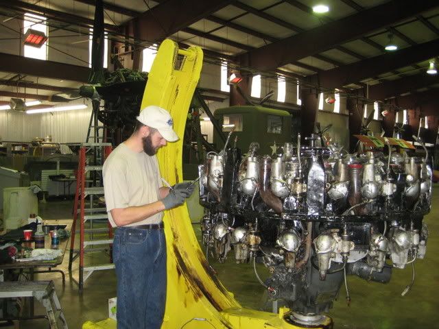
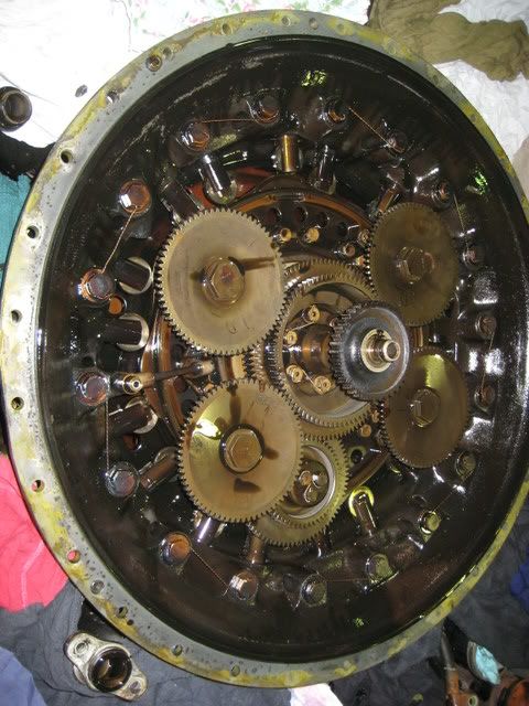
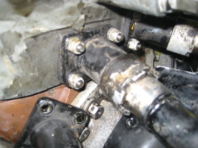
For those who haven't torn into one of these, I thought I'd show you what we had to do to get ready to separate this adapter case. Remember what this looked like from an earlier shot. To remove this, you need to take all those bolts out that are safety wired and pull/lift the case off. Before you do that, you have to get all those lifter rollers backed away from the cam and out of the way, so they will clear the gears when you lift it off.
So here is how that is done. First, take all the rocker box covers off all 9 of the rear cylinders. That's 18 if you're counting!
Then loosen the lock screw that holds the valve adjustment screw. Once loose, you back off the valve adustment screw all the way. 18 of those too!
Now you loosen the nuts on both ends of the push rod tubes. Yep, 18!!
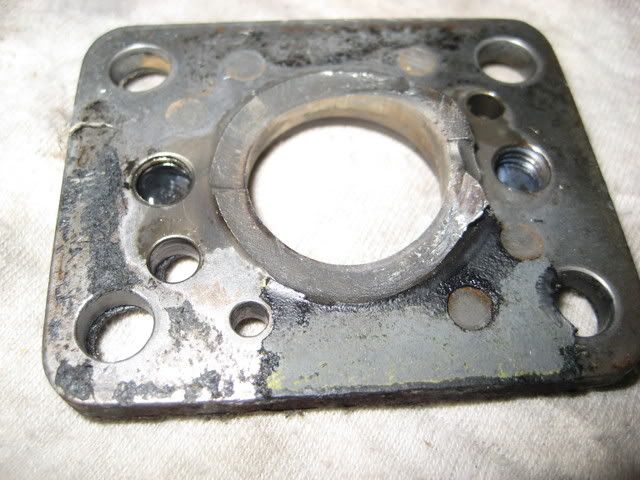
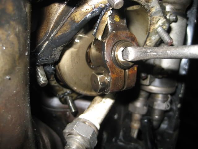
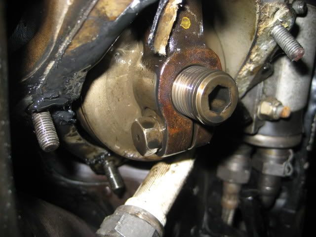
Now take all 4 of these nuts off the pushrod tube flange. 72 nuts in all!
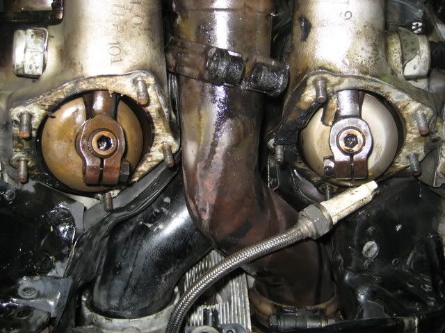
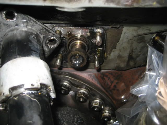
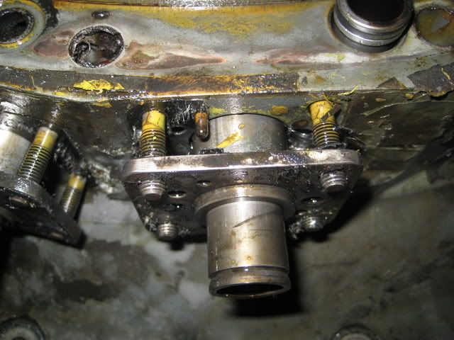
Once you have those off, you can slide the flange back enough to clear the studs. In order to do that, you take one hand and put it under the rocker arm and pull. This will depress the spring in the lifter. Then with your other hand, use a small screw driver to hold the depressed lifter thats right in there behind the flange. If you did this right, you can now let go of the rocker arm and work the pushrod tube away from its mounting studs.

When you get it cleared of the studs, you can grab the lifter and spring and pull it right out of the lifter housing.
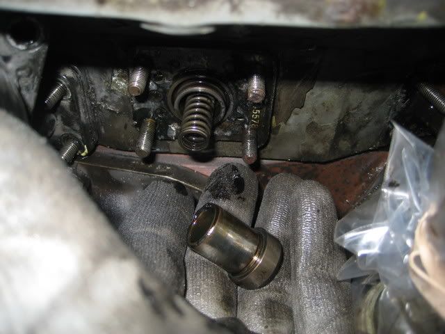
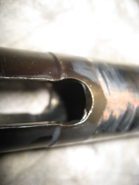
Then you get to wrestle with the push rod tube and the push rod. You see, you can't get the tube off/out from the other end until you get the pushrod pulled out far enough to clear the rocker box.
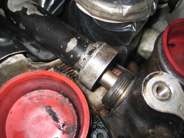
This is when you have to just move it around and hold your mouth just right, then it will come out. Ahh, got it! only 17 more to go.
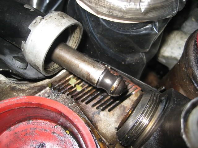
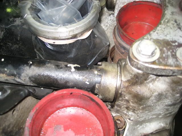
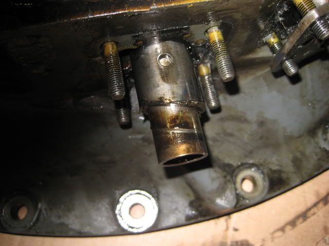
Now you can get the lifter housing loose and pulled away from the case so the lifter roller will be able to clear the gears which is why you had to go to all this trouble in the first place!!
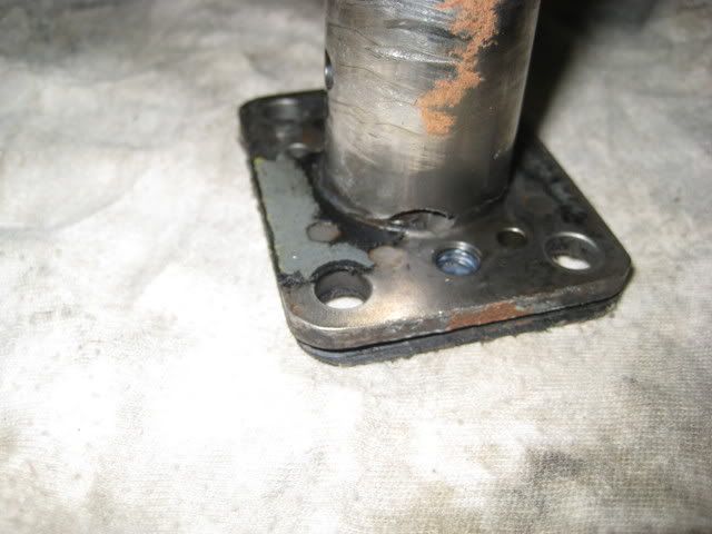
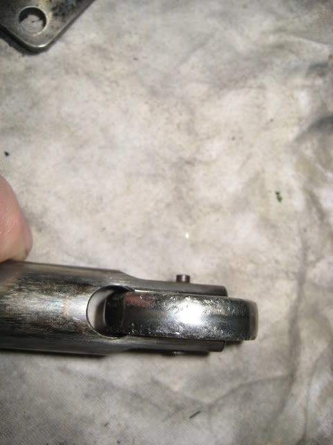
This was another one we found broken.
After all that, the only thing left was the oil tube, which I removed while Nolan, my help for today, took all the bolts out that hold it on. Then we popped the case off and prepared the new adapter case for assembly.
Old case.
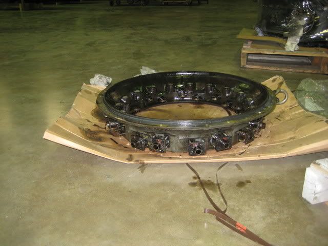
New case.

Finally, My trusty volunteer, Nolan putting the rocker box covers back on. He is a student at the A&P school here. He was a great help with this and I think he didn't mind getting dirty!
Thanks Nolan