Okay, since it's been two whole days since my last update, I thought I'd share with y'all what's been going on during that extended period of time.


Where I was during my last update is where I'm still at today. That freakin' entry door. I forgot to take photos of the bracketry on the left side of the door that will hold the door holder-upper stuff on, so here's how it went on the right side......
The first thing was to locate and drill the holes for the brackets that I had already made. I then clecoed the first piece into place......

The second bracket had yet to have it's holes located. In this picture, you can see how the hole-less bracket covers up the existing holes that I need to duplicate.......

The way I make those holes is with the use of a simple little tool, cleverly called a hole finder......

The way it works is you simply place the stud that's in the bottom of the tool into the hole you wish to duplicate......

Then you place the piece of metal that needs the hole drilled in it in between the two legs of the tool, and in it's desired location.......

The final step is to place your drill bit in the guide on the upper leg of the tool, and drill your hole......

Once the hole is drilled (and deburred), just cleco it into place and do the same with the next hole.......


After that, I located and drilled four holes on the outer edges, then shot some spray bomb zinc chromate on the bracket, and riveted it into place while the primer was still wet. Notice that I only filled the outer holes with rivets for now, since that large piece of skin is only temporarily installed and will come off later for more trimming, fitting, beefing up, and priming. If I had filled the center holes with rivets, that would be riveting both pieces to the door structure. That is also the reason the outside bracket isn't riveted on yet either.......

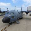
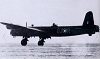
Okay...now that those brackets on both sides are in place, I had to make up some cables to use in this holder-upper arrangement. I'm using designs from our old step arrangement, along with the set-up that the B-23 sitting outside has on it. More on that later though.
Our old steps used a set of chains with a clear vinyl hose over the top of them for the handrail/holder-upper set-up. This worked pretty well, but they are too clunky and cumbersome for what I'm after. Remember, I'm trying to make this as hidden as possible when the door is shut, so that it looks like a waist gunner's position from the inside, not some silly door that doesn't belong there.

Have I mentioned I don't care for this doggone door?
Anyway........So what I came up with was some 3/16" cable that has a nice, thick vinyl coating on it to keep the fraying down to a minimum, along with not trashing people's hands when using them as a handrail. The way I went about making the cables up is as follows........
Naturally, I neglected to take pictures of the first cable I made, so you're going to join in on the second one. I started with laying the first cable out on the table and working out the length I needed for the second one.....

Because of the extra thickness of the protective coating, the swages that hold everything together wouldn't slide on the cable. Frankly, you wouldn't want that anyway. You need the swages to be directly on the cable itself so that it is as strong of a hold as possible. I had previously determined that 8" of this protective coating needed to be removed in order to make room for the "stuff" that needed to be installed......

I initially used a scalpel to cut the coating, and even though it worked for the section pictured here, it proved to be too flimsy for this stuff and I just used an X-acto knife from then on.........


Okay, I then needed to get the first cable I made and line it up with the new piece, minus the 8" for the end........

Then I marked the opposite end........

.......And added a second mark 8" further past the previous one. This will be the actual end of the cable. That previous mark will be the point where I remove the protective coating.........

The die grinder and carbon fiber cutoff wheel is ideal for cutting cables like this. Normally, I'd wrap tape or something similar around the area being cut, so that the cable won't fray, but this protective coating enabled me to not have to go through that step. Another trick is to hold tension on the cable while cutting to get a nice clean end......

The next step was to slide on a short lenth of heat shrink tubing (which we'll use in a little bit), along with the swage........

Then I fed the end of the cable through the other end of the swage, leaving room to get the thimble inside the loop.......

Now, since this wasn't being a big enough pain in the butt to have to do multiple times with four different cables total, this 3/16" cable is also difficult to work with. You have to get.....um.......creative, when trying to hold everything together when you're by yourself. The vice grips were only tight enough to hold the cables in place...you don't want to damage or marr anything...The hemostats were as tight as I could get them, which was barely tight enough
.........

The next step is to crimp the swage with....you guessed it.....a cable swager/crimping tool. The folks that name these tools really are geeeeniouses. Anyhow, since I was working alone, I had to place one of the handles on the table, while holding the other one with one hand and lining the swage up inside the tool with the other. I could then pull the handles together to crimp the swage onto the cable.........


I crimped the swage in two spots, just for added strength........

After that was done, I used the die grinder and sanding disc to remove the little sharp pieces of extra, unused cable from the end of the swage...

Then I slid that heat shrink tubing over the bare section of cable and heated it up with the heat gun, so that it is all sealed up from where I removed the protective coating........

And here's the finished end.......

In the middle of making up the next two, shorter cables, I had to stop what I was doing to answer numerous phone calls, go pick up some paint that we just had mixed, and help John take off a couple of cylinders. (With the light right above his head, it kind of looks like John had an idea right when I took this picture, huh?
)......


Eventually, I was able to finish building the cables and placed them in their proper locations on the door.......

So there you have it. Two freakin' days of very little progress. It's not that we're not trying, it's just that it seems like progress has stood still and Father Time has put everything in fast forward. I reckon it's time to start working the long hours, huh?

On another topic, during some of those phone calls earlier, I checked on the status of y'all's guns. They are being manufactured as we speak and should be ready soon. I'll keep you all posted on the progress of them as I hear more.
Gary


 Go Packers...hey!!!!!